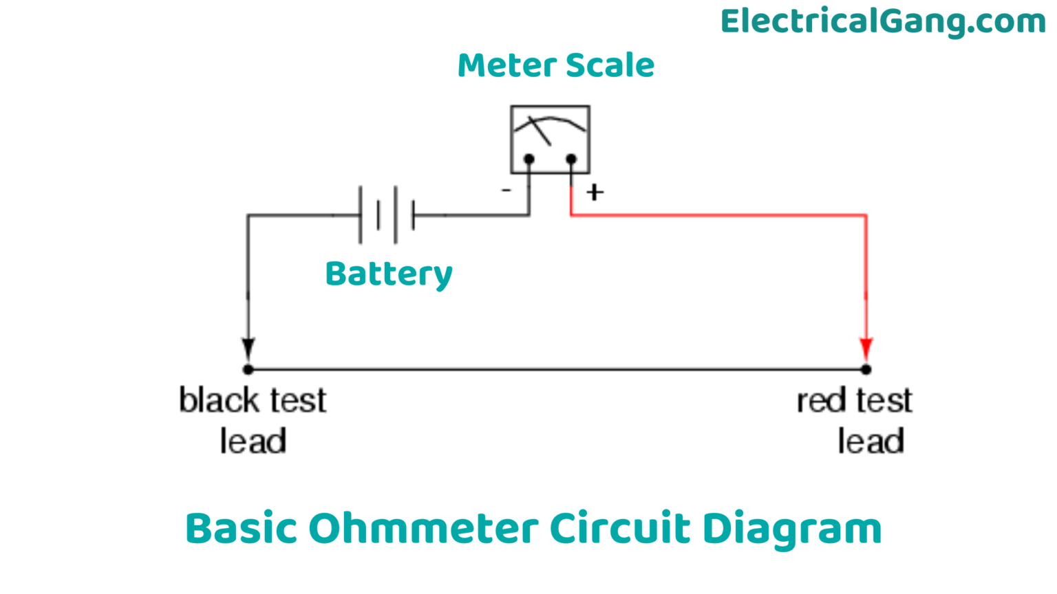
Diagram Of Ohmmeter. Ohmmeter is used to directly measure resistance of a device, element, circuit or any portion thereof. A simple explanation of an ohmmeter. This meter is used to determine approximate (not too accurate) resistance of the circuit components. The meter is used to measure the value of unknown resistance in ohms. The battery (e), basic meter (r m ) and the adjustable resistance are the main components of the shunt ohmmeter. Ohmmeters are essential tools for. The unit of resistance is the o. an ohmmeter is an electrical instrument that measures electrical resistance (the opposition offered by a circuit or. — an ohmmeter is a fundamental electrical device used to measure electrical resistance in a circuit. the circuit diagram of the shunt ohmmeter is shown in the figure below. — in this topic, you study the definition, working & diagram of ohmmeter. The unknown resistance is connected across terminal a and b. an ohm meter is a device used to measure the electrical resistance of a circuit or component. — construction, circuit diagram, types & working.
from electricalgang.com
A simple explanation of an ohmmeter. — in this topic, you study the definition, working & diagram of ohmmeter. Ohmmeters are essential tools for. the circuit diagram of the shunt ohmmeter is shown in the figure below. Ohmmeter is used to directly measure resistance of a device, element, circuit or any portion thereof. The unit of resistance is the o. The unknown resistance is connected across terminal a and b. The battery (e), basic meter (r m ) and the adjustable resistance are the main components of the shunt ohmmeter. The meter is used to measure the value of unknown resistance in ohms. an ohmmeter is an electrical instrument that measures electrical resistance (the opposition offered by a circuit or.
What is an Ohmmeter? Ohmmeter Working Principle Types of Ohmmeter
Diagram Of Ohmmeter A simple explanation of an ohmmeter. — an ohmmeter is a fundamental electrical device used to measure electrical resistance in a circuit. an ohmmeter is an electrical instrument that measures electrical resistance (the opposition offered by a circuit or. The battery (e), basic meter (r m ) and the adjustable resistance are the main components of the shunt ohmmeter. — construction, circuit diagram, types & working. Ohmmeter is used to directly measure resistance of a device, element, circuit or any portion thereof. The unknown resistance is connected across terminal a and b. — in this topic, you study the definition, working & diagram of ohmmeter. The unit of resistance is the o. The meter is used to measure the value of unknown resistance in ohms. an ohm meter is a device used to measure the electrical resistance of a circuit or component. Ohmmeters are essential tools for. This meter is used to determine approximate (not too accurate) resistance of the circuit components. the circuit diagram of the shunt ohmmeter is shown in the figure below. A simple explanation of an ohmmeter.